'96 - '02 4.3 CSFI to MPFI Injector upgrade kit.
Posted: Mon Sep 18, 2006 7:55 pm
Originally posted on A/S on April 04 2006,8:34
As some people have needed it, I have condensed a bulletin from GM so that everyone could access it. For the full version of this you will need bulletin #00-06-04-003B.
Note: If your vehicle has Californina Emissions (RPO code YF5) there is a special policy, (Kind of a recall, so free ) #99066G on the injectors for 10 years or 200,000 miles.
Rough Idle After Start, And/Or A Service Engine Soon (SES) Light (Unstick And Clean Central Sequential Fuel Injection (CSFI) Poppet Valves or Convert to MFI)
1996-2002 Chevrolet and GMC M/L Models with 4.3L, 5.0L or 5.7L Engine (VINs W, M, R -- RPOs L35, L30, L31)
Some owners may comment on rough idle after start-up, especially if the vehicle has sat overnight. These symptoms may be intermittent. The Service Engine Soon (SES) light may also be illuminated. Current misfire or history misfire codes may be detected with a scan tool.
Cause
A deposit build-up on the CSFI poppet valve ball and/or seat may cause the poppet ball to stick open or closed. In either case, the specific cylinder will be mis-fueled, resulting in a cylinder mis-fire condition.
Correction
A new MFI fuel system has been developed that will back service the CSFI fuel system. The MFI fuel system eliminates the CSFI poppet valve ball and seat. The CSFI fuel system will need to be replaced as a unit.
Notice: Individual CSFI injectors can not be replaced with MFI injectors. The entire CSFI fuel meter body will need to be replaced. The bracket used to retain the injectors in the fuel meter body is different between the CSFI and MFI unit. The unit may not seal if you mix injectors. Severe engine damage could result.
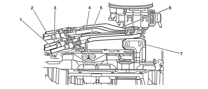
1. Remove Upper Intake Manifold plenum and SFI Fuel Meter Body.

(1) Cyl. #1 tube
(2) Cyl. #2 tube
(3) Cyl. #3 tube
(4) Cyl. #4 tube
(5) Cyl. #5 tube
(6) Cyl. #6 tube
(7) MFI Fuel Meter Body
2. Remove the Fuel Meter Body bracket and discard. Install the new bracket as shown in Figure 1.

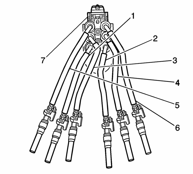
(1) Cyl. #1 tube
(2) Cyl. #2 tube
(3) Cyl. #3 tube
(4) Cyl. #4 tube
(5) Cyl. #5 tube
(6) Cyl. #6 tube
(7) MFI Fuel Meter Body
3. Position Fuel Tubes of MFI Fuel Meter Body as shown in Figure 2. Tubes must be oriented away from the fuel pressure regulator end of the fuel meter body.
Notice: The number 3 Fuel Tube must be positioned behind the number 1 Fuel Tube to eliminate interference with the Upper Intake Manifold plenum when installed. See Figure 2.
4. Insert the MFI Fuel Meter Body into the Fuel Meter Body Bracket on the Lower Intake Manifold being careful not to bind the Fuel Tubes. Make sure that the number three Fuel Tube is routed in behind number 1 and 5 Fuel Tubes as shown in Figure 2. Push down firmly on the fuel meter body locking it into the bracket.
Notice: Use caution when inserting injectors into lower intake manifold to be sure the correct injector is being placed into the correct hole. Injectors should not be removed once they have been installed. Removal of injectors from the intake manifold may cause damage to the retaining lugs on the injector.
Important: The Injector holes are numbered on the Lower Intake Manifold. The injectors are numbered on the side of the Fuel Meter Body.
5. Insert the number 3 injector into the correct Injector hole in the Lower Intake Manifold first. Install the number 5 injector next and then number 1. This sequence must be followed correctly to prevent interference of the Fuel Tubes. Injectors 2, 4, and 6 are then installed.
6. Insure that the electrical connectors of the injectors are positioned so that they do not interfere with each other and are pointing towards the center of the Intake Manifold. If necessary, rotate the electrical connectors inboard.
Notice: Lack of lubrication will make installation of the Upper Intake Manifold plenum difficult and may cause damage to the O-ring.
7. Lubricate the Fuel Meter Body Upper Manifold O-ring (orange in color) with clean engine oil.
8. Inspect the Upper Intake Manifold plenum gasket and replace if necessary. Reinstall the Upper Intake Manifold plenum.
Important: Lubricate the Fuel Inlet and Return Lines with clean engine oil before inserting them into the Fuel Meter Body. Make sure that the Fuel Line Retaining Bracket is properly oriented with the tabs down.
For some more information or cost on replacement checkout Lindertech injection service. They have some good information on reasons for upgrading & prices.
As some people have needed it, I have condensed a bulletin from GM so that everyone could access it. For the full version of this you will need bulletin #00-06-04-003B.
Note: If your vehicle has Californina Emissions (RPO code YF5) there is a special policy, (Kind of a recall, so free
Rough Idle After Start, And/Or A Service Engine Soon (SES) Light (Unstick And Clean Central Sequential Fuel Injection (CSFI) Poppet Valves or Convert to MFI)
1996-2002 Chevrolet and GMC M/L Models with 4.3L, 5.0L or 5.7L Engine (VINs W, M, R -- RPOs L35, L30, L31)
Some owners may comment on rough idle after start-up, especially if the vehicle has sat overnight. These symptoms may be intermittent. The Service Engine Soon (SES) light may also be illuminated. Current misfire or history misfire codes may be detected with a scan tool.
Cause
A deposit build-up on the CSFI poppet valve ball and/or seat may cause the poppet ball to stick open or closed. In either case, the specific cylinder will be mis-fueled, resulting in a cylinder mis-fire condition.
Correction
A new MFI fuel system has been developed that will back service the CSFI fuel system. The MFI fuel system eliminates the CSFI poppet valve ball and seat. The CSFI fuel system will need to be replaced as a unit.
Notice: Individual CSFI injectors can not be replaced with MFI injectors. The entire CSFI fuel meter body will need to be replaced. The bracket used to retain the injectors in the fuel meter body is different between the CSFI and MFI unit. The unit may not seal if you mix injectors. Severe engine damage could result.
1. Remove Upper Intake Manifold plenum and SFI Fuel Meter Body.

(1) Cyl. #1 tube
(2) Cyl. #2 tube
(3) Cyl. #3 tube
(4) Cyl. #4 tube
(5) Cyl. #5 tube
(6) Cyl. #6 tube
(7) MFI Fuel Meter Body
2. Remove the Fuel Meter Body bracket and discard. Install the new bracket as shown in Figure 1.

(1) Cyl. #1 tube
(2) Cyl. #2 tube
(3) Cyl. #3 tube
(4) Cyl. #4 tube
(5) Cyl. #5 tube
(6) Cyl. #6 tube
(7) MFI Fuel Meter Body
3. Position Fuel Tubes of MFI Fuel Meter Body as shown in Figure 2. Tubes must be oriented away from the fuel pressure regulator end of the fuel meter body.
Notice: The number 3 Fuel Tube must be positioned behind the number 1 Fuel Tube to eliminate interference with the Upper Intake Manifold plenum when installed. See Figure 2.
4. Insert the MFI Fuel Meter Body into the Fuel Meter Body Bracket on the Lower Intake Manifold being careful not to bind the Fuel Tubes. Make sure that the number three Fuel Tube is routed in behind number 1 and 5 Fuel Tubes as shown in Figure 2. Push down firmly on the fuel meter body locking it into the bracket.
Notice: Use caution when inserting injectors into lower intake manifold to be sure the correct injector is being placed into the correct hole. Injectors should not be removed once they have been installed. Removal of injectors from the intake manifold may cause damage to the retaining lugs on the injector.
Important: The Injector holes are numbered on the Lower Intake Manifold. The injectors are numbered on the side of the Fuel Meter Body.
5. Insert the number 3 injector into the correct Injector hole in the Lower Intake Manifold first. Install the number 5 injector next and then number 1. This sequence must be followed correctly to prevent interference of the Fuel Tubes. Injectors 2, 4, and 6 are then installed.
6. Insure that the electrical connectors of the injectors are positioned so that they do not interfere with each other and are pointing towards the center of the Intake Manifold. If necessary, rotate the electrical connectors inboard.
Notice: Lack of lubrication will make installation of the Upper Intake Manifold plenum difficult and may cause damage to the O-ring.
7. Lubricate the Fuel Meter Body Upper Manifold O-ring (orange in color) with clean engine oil.
8. Inspect the Upper Intake Manifold plenum gasket and replace if necessary. Reinstall the Upper Intake Manifold plenum.
Important: Lubricate the Fuel Inlet and Return Lines with clean engine oil before inserting them into the Fuel Meter Body. Make sure that the Fuel Line Retaining Bracket is properly oriented with the tabs down.
For some more information or cost on replacement checkout Lindertech injection service. They have some good information on reasons for upgrading & prices.


