Residential Wiring Advice II
-
Topic author - I plan to be buried in my van
- Posts: 2153
- Joined: Sun Sep 10, 2006 6:45 pm
- Location: Selah, WA
- Contact:
Residential Wiring Advice II
OK, I'm no electrician, but I've never hesitated tackling electrical jobs. I have a couple of decent books on wiring, know how to search the web for answers, and have just generally picked things up over the years.
But today I just can't wrap my head around what I've got...
Picture two bathrooms with overhead lights and seperate exhaust fans. Both bathrooms have two switches, one to control the light and one to control the fans. (The two switches are on a single gang device and share the double gang box with recepticles too.) Up until today, neither fan worked, so both were replaced. (Well, technically, at least one worked a bit... it would groan when the switch was on.)
After replacing one fan, I flipped the switch and the fan worked great. Note though that the light has to be on for the fan to run. Turning the light off shuts off the fan, regardless of the fan switch position.
I then moved on to the second fan. Once complete, I turned the fan switch on and nothing. Doesn't matter whether the light is on or off.
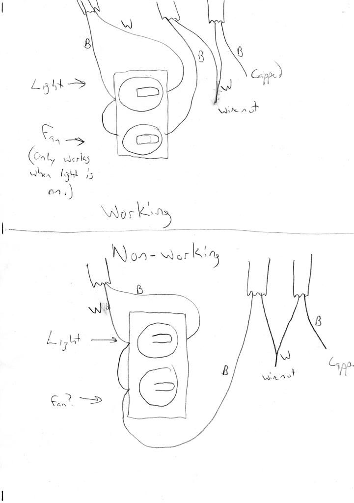
Below is a rough sketch of the way the two switches are currently wired. (I ommitted the ground wires for clarity.)
Note that both boxes contain a capped black wire. I found that if I touch the capped black wire for the non-working fan to the open terminal on the switch, the fan runs. (This is how I confirmed my new fan worked.)
After finding the one fan not working, that is when I went and pulled the cover off of the switch for the working fan. This is also when I discovered the switches were wired differently. Since someone in the past had replaced the switch for the non-working fan, I thought maybe they had just wired it up wrong. I temporarily rewired it like the working fan and it made no difference. (Well, that isn't totally true. I could use either switch to turn the light on, but the fan would never come on.)
The leads on my multi meter aren't long enough to check continuity and try and isolate all the wires. That is my next step, but I thought if I posted this up, someone might see something I'm missing.
Last edited by mdmead on Fri May 21, 2010 9:46 am, edited 1 time in total.
Matt
Selah, WA
-96 GMC Safari AWD Hi-Top Conversion -->Stalled 5.3L swap & 5" lift
-74 Ford Bronco -->Far from perfect but mine!
-99 V-10 Ford Super Duty Super Cab 4x4 -->Stock with 285 Cooper ATs
-00 Ford Focus Wagon -->The Red Turd
-95 Ford 24' Class C Motorhome -->My big block sleeper
-07 Can-Am Outlander XT -->My yellow 4x4 quad for work & play
-04 Ski Doo REV Summit -->Still several chassis behind!
No new projects until the current ones are done!
Re: Residential Wiring Advice II
Nice puzzle. I've got an idea:
On the "working" sketch
The cable on the top left looks like a switch tail. That said, usually the black is hot (line), and the white (which should be flagged with black tape as hot) should be on the other side of the switch (load) to return the hot to the fixture. (edit) The line is just tied to the other switch to power the fan.
The middle cable's black wire must go to the fan, and the fan should run whether the light is on or not unless the white wire is actually line and the black is load. No idea on what the right cable does.
On the "non-working" sketch
I noticed that the black and white were reversed on the switch, and that the white (which also should be marked as hot with black if that is the case) is bonded to the lower switch, which doesn't make sence unless the line and load are reversed. From there I can only guess that the middle cable is actually the unknown cable, and that the one on the right is the same as the center cable in the "working" sketch, and feeds the fan.
Only a guess from a
-
- I have my van tatooed on my cheeks
- Posts: 4379
- Joined: Sat Sep 09, 2006 3:35 pm
- Location: New Haven, NY
Re: Residential Wiring Advice II
What switch is controlling the light and which is controlling the fan? Are there any other switches that turn on either the light or fan...ie 2 way switches?
Lets fix the working light and fan first. The fan should come on whether or not the light is on. What you should have is a supply wire coming up to the box. The black from that should feed both switches on one side. The white should be the neutral and the neutral from the fan and light should be tied to that. It won't be tied to the switch at all. What you want is 2 cables coming from the fan/light so you can feed each separately from the switch.
Tip...
If you want to test continuity in a single cable, tie one end of the wires together and find the other end with your meter. Of course power and all wires must be disconnected.
Tip 2...
If you want longer leads on your meter so you can reach farther, just add a length of wire to the lead and wire nutting the other end (or use a helper) to the suspect wire. Your meter leads can then be as long as you want.
Current rides:
2013 Toyota Tundra DC 4x4
2008 Dodge Nitro 4x4
2005 Nissan Sentra 1.8S Special Edition
Mileage spreadsheet
Vans owned:
1986 Safari 2.5L 4 speed manual - scrapped
1995 Astro 2WD conversion 4.11 posi, shift kit, DHC rock rails - sold to Skippy
1998 Astro 4x4 D44, D60, NP231, full hydraulic system with 9k# Milemarker winch and snow plow - sold to Lockdoc
2003 Astro AWD all stock - traded for a 3/4 ton truck
2005 AWD, 4.10's - sold to skippy
-
Topic author - I plan to be buried in my van
- Posts: 2153
- Joined: Sun Sep 10, 2006 6:45 pm
- Location: Selah, WA
- Contact:
Re: Residential Wiring Advice II
Thanks for the thoughts so far guys!
I don't know why I didn't label the light & fan switches when I drew it up... I updated it and the info is above.
Regarding the fan that works (with the light on), I suspect it was wired that way on purpose originally... I'm not sure why though. But I've got to think the capped black wire is a clue on this.
Matt
Selah, WA
-96 GMC Safari AWD Hi-Top Conversion -->Stalled 5.3L swap & 5" lift
-74 Ford Bronco -->Far from perfect but mine!
-99 V-10 Ford Super Duty Super Cab 4x4 -->Stock with 285 Cooper ATs
-00 Ford Focus Wagon -->The Red Turd
-95 Ford 24' Class C Motorhome -->My big block sleeper
-07 Can-Am Outlander XT -->My yellow 4x4 quad for work & play
-04 Ski Doo REV Summit -->Still several chassis behind!
No new projects until the current ones are done!
Selah, WA
-96 GMC Safari AWD Hi-Top Conversion -->Stalled 5.3L swap & 5" lift
-74 Ford Bronco -->Far from perfect but mine!
-99 V-10 Ford Super Duty Super Cab 4x4 -->Stock with 285 Cooper ATs
-00 Ford Focus Wagon -->The Red Turd
-95 Ford 24' Class C Motorhome -->My big block sleeper
-07 Can-Am Outlander XT -->My yellow 4x4 quad for work & play
-04 Ski Doo REV Summit -->Still several chassis behind!
No new projects until the current ones are done!
-
- I sleep in my van
- Posts: 285
- Joined: Sat Oct 13, 2007 6:39 am
- Location: Calgary, Alberta, Canada
Re: Residential Wiring Advice II
I agree with Lifted - find your power(hot) and common in and 2 wires to each device (assuming it is wired this way). The only thing I can think of, and I am not familiar with those 2 switch receptacle is that power does not flow through the device unless both switch are flipped - that said your drawing shows power (wire) going to both switches on the hot side so I do not believe this is the case.
First the working one – notice the black wire (hot) is going to BOTH switches on the same side (there might be a little knock out piece of metal between terminals on the switch itself that does this also). This is correct in my mind. Neutral (white wire) should go into the box and terminate with the additional 2 white wires from the fan and the light in the box with an appropriate wire nut and be twisted together. Of course ground should also be bonded for each device. This moves me to the white wire on the WORKING switches – I believe this to be running to a device – AKA Power is not supplied to the switches but rather to the device and then interrupted at the switch.
My advise – find and label your drawings to tell us which wire SUPPLIES power and then we can be of more help. Without this info it is simply a stab in the dark. Also try to label the wires going to the light and the fan. I am thinking supply power goes to the light then the switch interrupts the supply and then only if the light is on can power continue to the fan.
2001 Astro LT AWD - SOLD @ 180,200KM
Now I got a 2006 Ford Expedition King Ranch 4 x 4
to pull a Hybrid RV - 2006 Kodiak 235
Calgary, Alberta
Now I got a 2006 Ford Expedition King Ranch 4 x 4
to pull a Hybrid RV - 2006 Kodiak 235
Calgary, Alberta
-
Topic author - I plan to be buried in my van
- Posts: 2153
- Joined: Sun Sep 10, 2006 6:45 pm
- Location: Selah, WA
- Contact:
Re: Residential Wiring Advice II
OK, studying my pic, on the working light/fan, I have a guess on most of the wiring. The white wire probably should be identified with black tape as I'm guessing it is hot coming down to the switch. The black wire is hot when the switch is on taking the power back up to the light. That would explain why the fan only works when the light switch is on... that is the only time the left side of the switch has power. The middle wires would be black (hot) powering the vent and the neutral tied to the other neutral and leading... somewhere. The final black is probably hot, but not sure why it is there. Just along for the ride maybe since a neutral was needed for the fan at some point.
Assuming this is right... I'm too lazy to go and verify it tonight... I now need to think a little harder on the non-working fan.
Matt
Selah, WA
-96 GMC Safari AWD Hi-Top Conversion -->Stalled 5.3L swap & 5" lift
-74 Ford Bronco -->Far from perfect but mine!
-99 V-10 Ford Super Duty Super Cab 4x4 -->Stock with 285 Cooper ATs
-00 Ford Focus Wagon -->The Red Turd
-95 Ford 24' Class C Motorhome -->My big block sleeper
-07 Can-Am Outlander XT -->My yellow 4x4 quad for work & play
-04 Ski Doo REV Summit -->Still several chassis behind!
No new projects until the current ones are done!
Selah, WA
-96 GMC Safari AWD Hi-Top Conversion -->Stalled 5.3L swap & 5" lift
-74 Ford Bronco -->Far from perfect but mine!
-99 V-10 Ford Super Duty Super Cab 4x4 -->Stock with 285 Cooper ATs
-00 Ford Focus Wagon -->The Red Turd
-95 Ford 24' Class C Motorhome -->My big block sleeper
-07 Can-Am Outlander XT -->My yellow 4x4 quad for work & play
-04 Ski Doo REV Summit -->Still several chassis behind!
No new projects until the current ones are done!
Re: Residential Wiring Advice II
BLK supply wire FROM breaker box goes to
BOTH terminals on ONE side of the dual switch.
BLK wires on the OUTPUT side of the switch are NOT
tied together. Each BLK wire on the OUTPUT side goes
to it's individual load (fan or lamp).
WHI supply wire FROM breaker box goes to
BOTH the WHI wire to lamp and WHI wire to fan (WHI wires all tied together)
GRN (or bare copper/alum) wire (GROUND) goes to metal junction box, some switches (with GRN ground screw) and to GRN/copper/alum GROUND wire on both fan and lamp (ALL ground wires tied together and to all metal boxes).
If you have AC outlets in the same box, then pull a BLK and a WHI wire from the SUPPLY wires BEFORE the switch(s) and use those BLK/WHI wires to supply "always live" AC power to the outlets. BLK wire goes to the BRASS terminal on outlets (in USA), WHI wire goes to NICKEL terminal. GRN/copper/alum wire goes, as always, to GRN screw, metal box, all other ground wires.
If this is in a bathroom, it probably requires a GFI outlet rather than a standard outlet. Wiring is just as simple there. Instructions on the box and sometimes printed on the GFI outlet itself.
In simple terms, you're switching the HOT supply (the BLK wire) to either or both of the two loads (fan and lamp) the COLD supply (the WHI wire) and GROUND get connected directly to the loads on their WHI and GROUND wires, they are NOT switched but always connected.
And critically important is that the GROUND wires are ALL tied together AND bonded to the metal box.
Hope some of that makes sense.
Lumpy
-
Topic author - I plan to be buried in my van
- Posts: 2153
- Joined: Sun Sep 10, 2006 6:45 pm
- Location: Selah, WA
- Contact:
Re: Residential Wiring Advice II
Oh, I do understand all of this Lumpy. I'm just trying to figure out what I've got in my boxes and why!Lumpy wrote:And critically important is that the GROUND wires are ALL tied together AND bonded to the metal box.
Hope some of that makes sense.
Lumpy
I've always found general wiring easy to understand. What can be more difficult is trying to figure out what someone else did... especially when it is hidden in the wall.
I still haven't done any more troubleshooting on this... it is easier to wait until Monday when the ladies are out of the house before I turn the power back off...
Thanks to everyone for the input so far. I should have the answer tomorrow.
Matt
Selah, WA
-96 GMC Safari AWD Hi-Top Conversion -->Stalled 5.3L swap & 5" lift
-74 Ford Bronco -->Far from perfect but mine!
-99 V-10 Ford Super Duty Super Cab 4x4 -->Stock with 285 Cooper ATs
-00 Ford Focus Wagon -->The Red Turd
-95 Ford 24' Class C Motorhome -->My big block sleeper
-07 Can-Am Outlander XT -->My yellow 4x4 quad for work & play
-04 Ski Doo REV Summit -->Still several chassis behind!
No new projects until the current ones are done!
Selah, WA
-96 GMC Safari AWD Hi-Top Conversion -->Stalled 5.3L swap & 5" lift
-74 Ford Bronco -->Far from perfect but mine!
-99 V-10 Ford Super Duty Super Cab 4x4 -->Stock with 285 Cooper ATs
-00 Ford Focus Wagon -->The Red Turd
-95 Ford 24' Class C Motorhome -->My big block sleeper
-07 Can-Am Outlander XT -->My yellow 4x4 quad for work & play
-04 Ski Doo REV Summit -->Still several chassis behind!
No new projects until the current ones are done!
-
Topic author - I plan to be buried in my van
- Posts: 2153
- Joined: Sun Sep 10, 2006 6:45 pm
- Location: Selah, WA
- Contact:
Re: Residential Wiring Advice II
OK, I figured it out today and wired up the fan.
I isolated the right hand cable, wired the black and white together at the fan as suggested by Dean and checked continuity at the box. This confirmed this wiring was for the fan.
Pushing that cable aside, I unwired the switch and turned the power back on and started checking wire pairs for 120v. It's interesting the readings I got with light bulbs still installed in the fixtures vs not installed. In the end, I determined the left cable is wired like the left cable in the other bathroom. The white is hot down to the switch and the black takes it back to the lights. The middle cable is a hot black with a white neutral. (The white just about had to be a neutral wire since it was wired to the right cable's white wire too.)
So it looks like somebody disconnected the fan's hot wire on purpose and capped it. Probably because the fan wasn't working, or if it was, was making bad noises like the other one was.
I ended up removing the metal tab that connected both switches on the left side and left the top wired as it was. The bottom continues to use the black hot wire on the left and I then wired up the black from the far right cable to the right side of the switch.
Basically, both switch boxes appear to have all the same wires coming in, although I have them wired differently. In the non-working bathroom, I could have reversed the white and black wires from the left cable, capped the black wire from the middle cable, and then hooked up the right cable's black wire (on the same side as the other black wire), and I would have had the same operation I currently have in the other bathroom. (Fan only works if the light is on too.)
(Or I could go back to the other bathroom and hook up the capped black wire and remove the metal connector between the switch and have the fan work independently........)
Bottom line: Both fans work and the house shouldn't catch fire due to improper wiring!
Matt
Selah, WA
-96 GMC Safari AWD Hi-Top Conversion -->Stalled 5.3L swap & 5" lift
-74 Ford Bronco -->Far from perfect but mine!
-99 V-10 Ford Super Duty Super Cab 4x4 -->Stock with 285 Cooper ATs
-00 Ford Focus Wagon -->The Red Turd
-95 Ford 24' Class C Motorhome -->My big block sleeper
-07 Can-Am Outlander XT -->My yellow 4x4 quad for work & play
-04 Ski Doo REV Summit -->Still several chassis behind!
No new projects until the current ones are done!
Selah, WA
-96 GMC Safari AWD Hi-Top Conversion -->Stalled 5.3L swap & 5" lift
-74 Ford Bronco -->Far from perfect but mine!
-99 V-10 Ford Super Duty Super Cab 4x4 -->Stock with 285 Cooper ATs
-00 Ford Focus Wagon -->The Red Turd
-95 Ford 24' Class C Motorhome -->My big block sleeper
-07 Can-Am Outlander XT -->My yellow 4x4 quad for work & play
-04 Ski Doo REV Summit -->Still several chassis behind!
No new projects until the current ones are done!
-
- I have my van tatooed on my cheeks
- Posts: 4379
- Joined: Sat Sep 09, 2006 3:35 pm
- Location: New Haven, NY
Re: Residential Wiring Advice II
Glad you get it figured out!
Current rides:
2013 Toyota Tundra DC 4x4
2008 Dodge Nitro 4x4
2005 Nissan Sentra 1.8S Special Edition
Mileage spreadsheet
Vans owned:
1986 Safari 2.5L 4 speed manual - scrapped
1995 Astro 2WD conversion 4.11 posi, shift kit, DHC rock rails - sold to Skippy
1998 Astro 4x4 D44, D60, NP231, full hydraulic system with 9k# Milemarker winch and snow plow - sold to Lockdoc
2003 Astro AWD all stock - traded for a 3/4 ton truck
2005 AWD, 4.10's - sold to skippy
2013 Toyota Tundra DC 4x4
2008 Dodge Nitro 4x4
2005 Nissan Sentra 1.8S Special Edition
Mileage spreadsheet
Vans owned:
1986 Safari 2.5L 4 speed manual - scrapped
1995 Astro 2WD conversion 4.11 posi, shift kit, DHC rock rails - sold to Skippy
1998 Astro 4x4 D44, D60, NP231, full hydraulic system with 9k# Milemarker winch and snow plow - sold to Lockdoc
2003 Astro AWD all stock - traded for a 3/4 ton truck
2005 AWD, 4.10's - sold to skippy
Re: Residential Wiring Advice II
X2
Your project crossed my mind tonight while I was wiring up and mounting the baseboard heaters in my addition. I also thought about WACK and his A/C baseboard heater ordeal. Funny how your mind wanders while you work.
-
- I sleep in my van
- Posts: 285
- Joined: Sat Oct 13, 2007 6:39 am
- Location: Calgary, Alberta, Canada
Re: Residential Wiring Advice II
Cheers! However I warn (someone told me I am a building inspector) that the power distribution doesn't seem right! Please NOTE I am NOT an electrical inspector but mark those hot white wires! It confirms that power is not going to the switch, rather one of the appliances most likely the light! Glad all is working - not a safety thing for sure just a marking item and getting er done.
2001 Astro LT AWD - SOLD @ 180,200KM
Now I got a 2006 Ford Expedition King Ranch 4 x 4
to pull a Hybrid RV - 2006 Kodiak 235
Calgary, Alberta
Now I got a 2006 Ford Expedition King Ranch 4 x 4
to pull a Hybrid RV - 2006 Kodiak 235
Calgary, Alberta
-
Topic author - I plan to be buried in my van
- Posts: 2153
- Joined: Sun Sep 10, 2006 6:45 pm
- Location: Selah, WA
- Contact:
Re: Residential Wiring Advice II
Yeah, I must confess I didn't mark the two white leads once I figured them out and I should have. But I'll be replacing both of those switches (color change) in the next few months and can do it then. I'm not really impressed with the way the wiring is in both of these bathrooms, but since it has been in place since the early 70s, I guess I'm not going to worry about it.thevalleyboy wrote:Cheers! However I warn (someone told me I am a building inspector) that the power distribution doesn't seem right! Please NOTE I am NOT an electrical inspector but mark those hot white wires! It confirms that power is not going to the switch, rather one of the appliances most likely the light! Glad all is working - not a safety thing for sure just a marking item and getting er done.
Matt
Selah, WA
-96 GMC Safari AWD Hi-Top Conversion -->Stalled 5.3L swap & 5" lift
-74 Ford Bronco -->Far from perfect but mine!
-99 V-10 Ford Super Duty Super Cab 4x4 -->Stock with 285 Cooper ATs
-00 Ford Focus Wagon -->The Red Turd
-95 Ford 24' Class C Motorhome -->My big block sleeper
-07 Can-Am Outlander XT -->My yellow 4x4 quad for work & play
-04 Ski Doo REV Summit -->Still several chassis behind!
No new projects until the current ones are done!
Selah, WA
-96 GMC Safari AWD Hi-Top Conversion -->Stalled 5.3L swap & 5" lift
-74 Ford Bronco -->Far from perfect but mine!
-99 V-10 Ford Super Duty Super Cab 4x4 -->Stock with 285 Cooper ATs
-00 Ford Focus Wagon -->The Red Turd
-95 Ford 24' Class C Motorhome -->My big block sleeper
-07 Can-Am Outlander XT -->My yellow 4x4 quad for work & play
-04 Ski Doo REV Summit -->Still several chassis behind!
No new projects until the current ones are done!