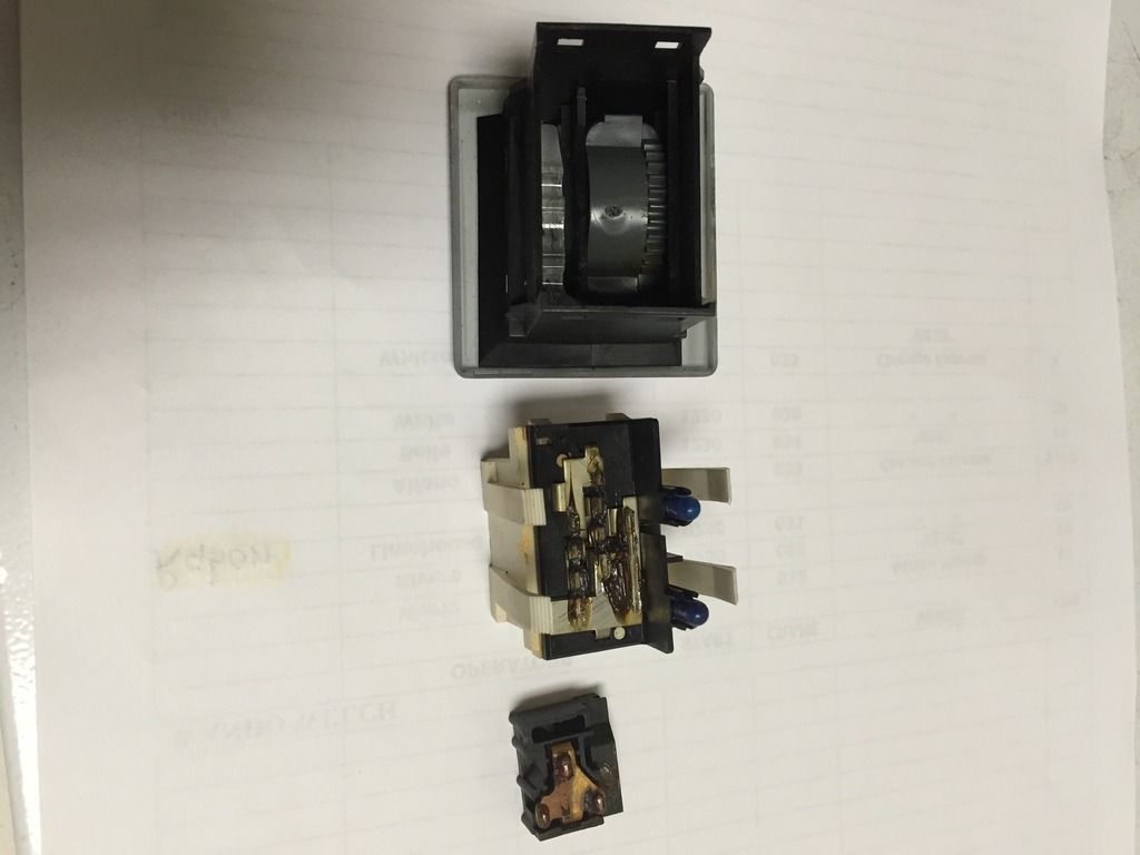
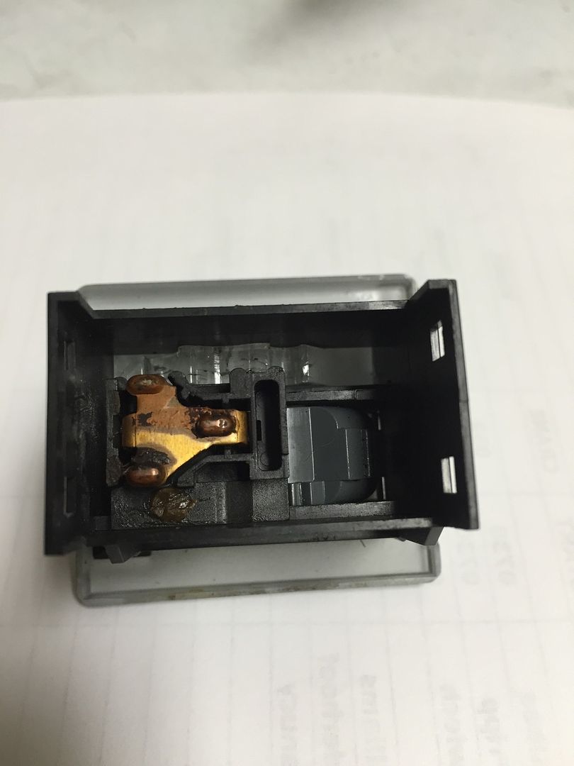
The contact board is separated from the main body by GENTLY pulling the ends of the main body out enough to release the catches of the contact board. Disassemble the switch with it in the off position and facing down so that the contact board lifts up and out after releasing the catches from the body. You'll see how the sliding contact is geared to the thumb wheel and that it has a small Chanel that rides on a rail that's part of the main body.
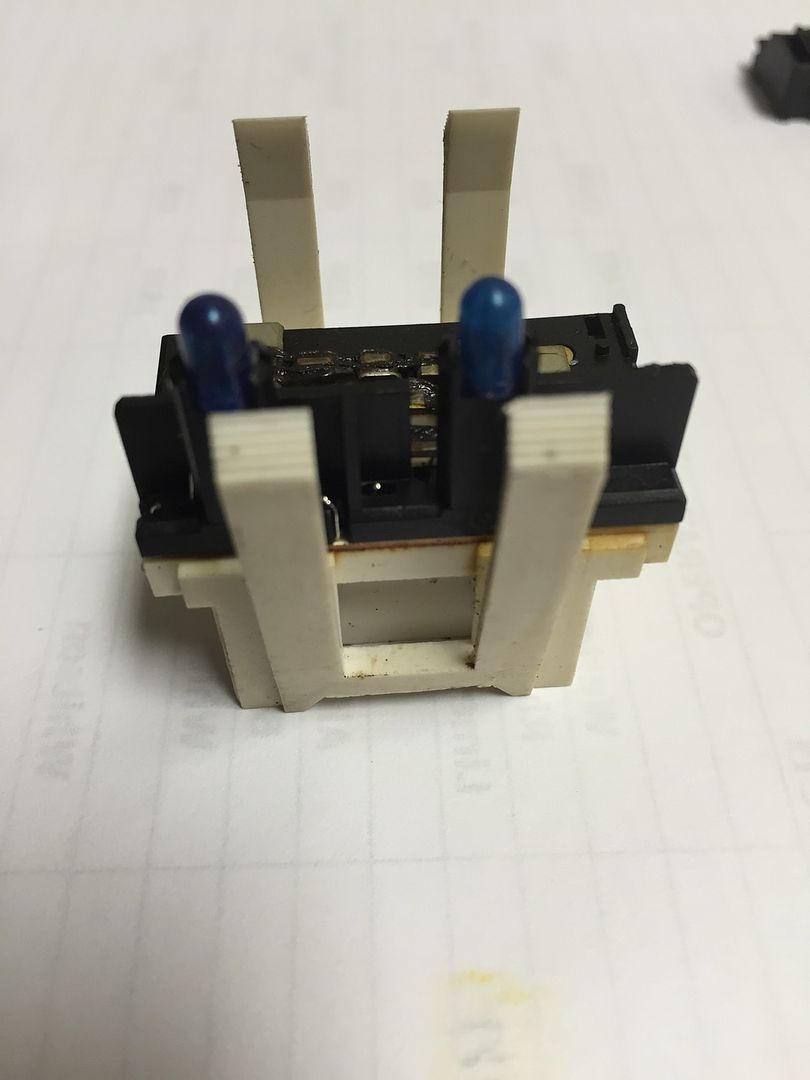
Now you'll be working in the main contact board that has the actual bulbs affixed to it. Start by removing the blue silicone covers from the bulbs.
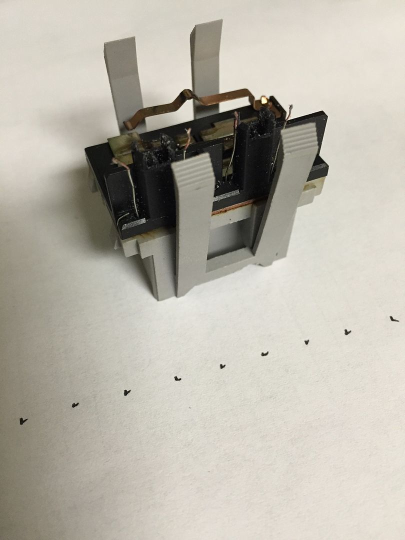
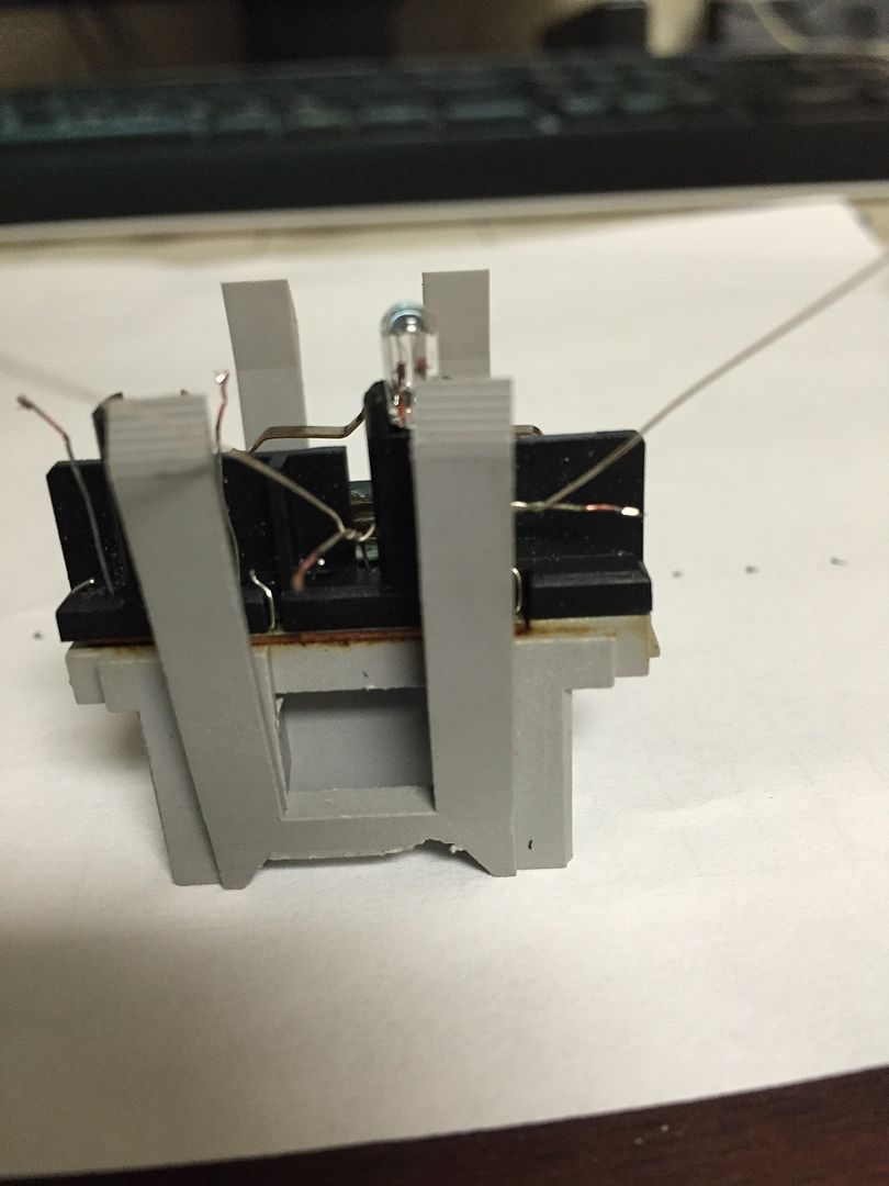
Wearing safety glasses and protective gloves, take a small pair of needle nose pliers and crush the bulbs! You want all the glass removed so that all you have left are the wire leads that went into the bulbs. it should look something like this:
Now take your new bulbs and feed the wire leads into the slots of the pedestals that the original bulbs sat in. Take each lead and carefully twist it to the standing wires you were left with when you crushed the bulbs. Long mini needle nose pliers make this part easier. Should look like this:
Once you have both bulbs in place and the leads twisted together, just a quick touch of your soldering pencil and dab of solder on the twisted leads will complete the connection. Use your mini cutters to trim the leads as close to the bulb towers as possible without breaking your just completed solder connection. Replace the blue silicone covers back over the bulbs, gently working them all the way down to the base of the bulbs. Now it's time to reassemble your re lamped switch. With the switch in the off position, facing down, your sliding contact MUST be correctly geared to the thumb wheel so that all speeds will work correctly once completed. There should be about a 1/16th of an inch clearance between the left side of the sliding contact and main body of the switch. If its actually touching the body of the switch on the left side, you will NOT have low speed!! In other words, move the sliding contact ONE tooth to the right to achieve that gap. ALSO, make sure the little channeled grove in the sliding contact is in the rail that runs along the side of the housing opposite if were the lamps fit into. That part of the slider should sit flush to the switch housing. If you did everything correctly, you should have this, along with all functioning fan speeds. Test to make sure you have all fan speeds before placing your switches back into your dash.
Hope this helps.
Cheers